 中文
中文 English
 Wenzhou Jiahao Petroleum Machinery .Ltd
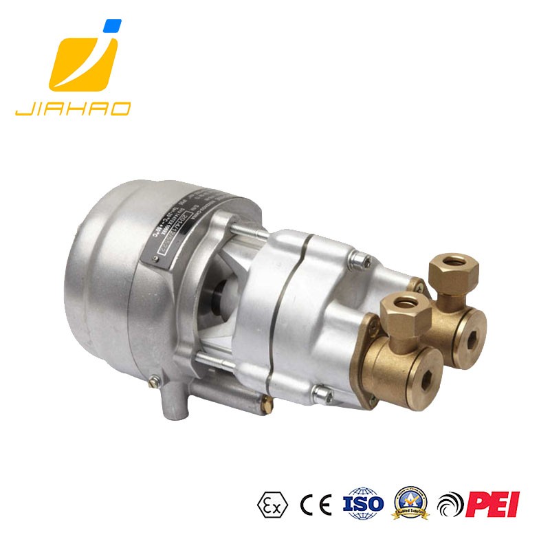
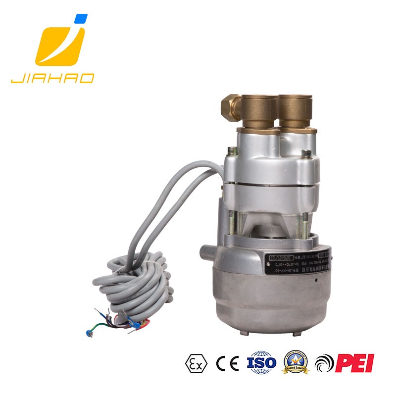
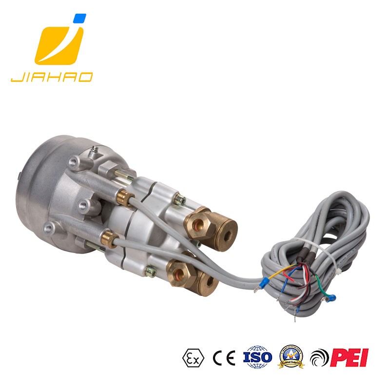
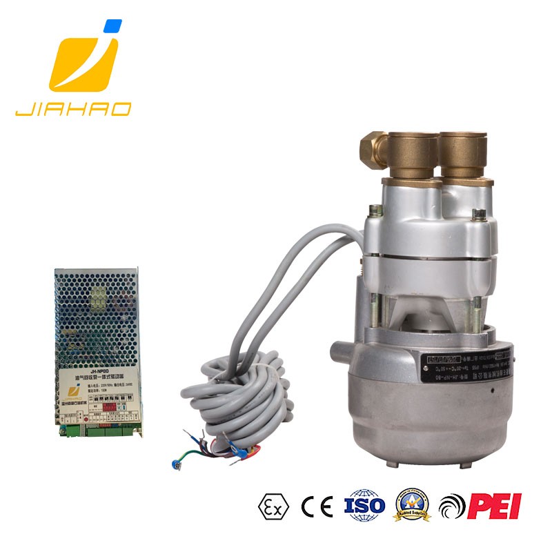
NP-80 VAPOR RECOVERY VACUUM NP PUMP

A: The cylinder rotation is flameproof, the length L of the flameproof joint surface is greater than or equal to 12. 5mm, the gap ic is less than or equal to 45mm, the small axial gap K is greater than or equal to 0.05mm, and the axial gap m when the K value is included is less than or equal to 0.30 mm.
Location B: The thread is explosion-proof, the thread is screwed into the depth pen 8 mm, the number of screwed buckles is greater than or equal to 5 buckles, and the thread matching accuracy grade is 6H/6g.
At C. Flame arrestor is used, the flame of the inlet pipe will not enter the vacuum pump through the barrier of the flame arrester, and the flame in the vacuum pump will not enter the outlet pipe after the barrier of the flame arrester.
Precautions for installation and operation
3.1 Do not destroy the vacuum packaging before installation.3.2 Do not pull the power cord of the motor.
3.3 The flame arrestor should be kept clean during use, and the air inlet should not be obstructed by dust and fibers.
3.3 Attention should be paid to the tightening of the connecting pieces when the pipeline is connected; the connecting parts of the gas circuit should be reliably sealed.
3.4 When connecting the pipeline, make sure that the filter is at the inlet end.
3.5 Do not disassemble or replace the lead compression nut at the outlet of the motor control line and feedback line without authorization.
3.6 There should be no intermittent or abnormal sound or vibration when the motor is running with no load or load.
3.7 When the thermal protection device and short-circuit protection device of the motor continuously actuate, the cause of the failure should be checked. (Whether it comes from the motor or overload or because the setting value of the protection device is too low). After the fault is eliminated, it can be put into operation.
3.8 During operation, the temperature rise of the casing measured with a thermometer generally does not exceed 190°C. The voltage of the motor is not allowed to exceed 10% of the full voltage, and the temperature of the sucked oil and gas must not exceed 50°C.
3.9 Certificate of good lubrication during the operation of the motor bearing, generally the motor runs for about 2000 hours, that is, the grease should be added or replaced (the closed bearing does not need to be replaced during the service life of the grease)
4. Installation site and installation foundation
4.1 The installation site of the NP pump should be dry and clean. The surrounding area of the NP pump should be well ventilated. There should be a certain interval with other equipment to facilitate inspection, monitoring and cleaning. The ambient temperature should be below 55t and strong radiation should be prevented.
4.2 The pump should be installed horizontally, the installation foundation should be sturdy, with a certain rigidity, and the installation surface should be flat to ensure the balanced operation of the motor;
4.3 The waterproof rating of the body for NP pump installation is at least IP23.
5. Installation of NP pump
5.1 The motor power cord is introduced through an explosion-proof junction box or other explosion-proof approved methods, and the installation complies with explosion-proof specifications.
5.2 In addition to the grounding wire inside the motor power cord, there is a grounding terminal and grounding screw on the motor shell. Here, a yellow-green two-color grounding wire> 4mm2 is required to connect to the general grounding point. And this grounding wire, avoid placing it in a place that is easily damaged by machinery, or other places that are easily damaged by vibrations, heat sources, etc.
5.3 In addition, the inspection and maintenance of the NP pump should meet the requirements of the "GB3836.15-2000 Electrical Equipment for Gas Environment Part Q-Electrical Installation in Hazardous Locations".
6. Inspection and maintenance of NP pump
6.1 Check whether the compression nuts at the cable wires of the two advance motors are loose; if they are loose, tighten them with a torque of 4Nm.
6.2 Check the flame arrestor, there must be no impurities, no disassembly and other normal conditions.
6.3 If other abnormal conditions are found, such as cable damage, etc., the pump must be returned to JIAHAO or its authorized company.
6.4 Because the pump is an explosion-proof product, it must not be repaired. If it needs to be repaired, it must be returned to JIAHAO or its authorized company and replaced with original parts.
6.5 In addition, the inspection and maintenance of the NP pump should meet the requirements of the standard of "GB3836.16-2006 Electrical Equipment for Gas Intense Environment-Inspection and Maintenance".
About us


